Home

Wegbringen Heer Persönlichkeit ideal battery Semester Mir Wesen

Tenergy 12V Battery Pack Bundle with Fast Charger Ideal for DIY Projects,  Medical Equipments, LED Light Kit, RC Models, Portable 12V DC Devices and  More
Tenergy 12V Battery Pack Bundle with Fast Charger Ideal for DIY Projects, Medical Equipments, LED Light Kit, RC Models, Portable 12V DC Devices and More
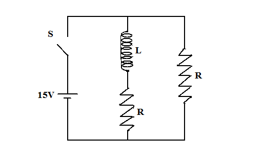
In the figure shown, a circuit contains two identical resistors with  resistance $R = 5\\Omega $ and an inductance with $L = 2mH$. An ideal  battery of $15V$ is connected in the
In the figure shown, a circuit contains two identical resistors with resistance $R = 5\\Omega $ and an inductance with $L = 2mH$. An ideal battery of $15V$ is connected in the

AAA Battery for Phone, Pack of 4 AAA Batteries Rechargeable Ideal for  Cordless Phones, No Memory Effect, 1.2 Volt , Low Self-Discharge,  Ready-to-Use: Amazon.de: Electronics & Photo
AAA Battery for Phone, Pack of 4 AAA Batteries Rechargeable Ideal for Cordless Phones, No Memory Effect, 1.2 Volt , Low Self-Discharge, Ready-to-Use: Amazon.de: Electronics & Photo

Ideal vs Real Battery Ideal battery: no internal energy dissipation - ppt  download
Ideal vs Real Battery Ideal battery: no internal energy dissipation - ppt download

In Figure, the ideal batteries have emfs E1 = 10.0V and E2 = 0.500 E1 , and  the resistances are each 4.00Ω . What is the current in (a) resistance 2  and (b) resistance 3?
In Figure, the ideal batteries have emfs E1 = 10.0V and E2 = 0.500 E1 , and the resistances are each 4.00Ω . What is the current in (a) resistance 2 and (b) resistance 3?
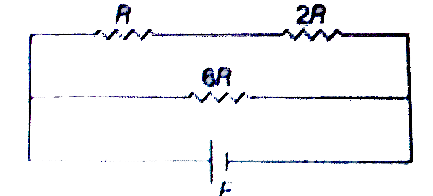
In the circuit shown, total power supplied by an ideal battery is 80 W. if  R = 10 Omega. Then Ratio of power developed across R, 2R and 6R will be
In the circuit shown, total power supplied by an ideal battery is 80 W. if R = 10 Omega. Then Ratio of power developed across R, 2R and 6R will be

Battery Construction | Batteries And Power Systems | Electronics Textbook

Ampere Time 12 V 50 Ah lithium LiFePO4 battery, ideal replacement for 12 V  100 Ah
Ampere Time 12 V 50 Ah lithium LiFePO4 battery, ideal replacement for 12 V 100 Ah

Ideal Battery Working Range: For optimal battery characteristics, the... |  Download Scientific Diagram
Ideal Battery Working Range: For optimal battery characteristics, the... | Download Scientific Diagram

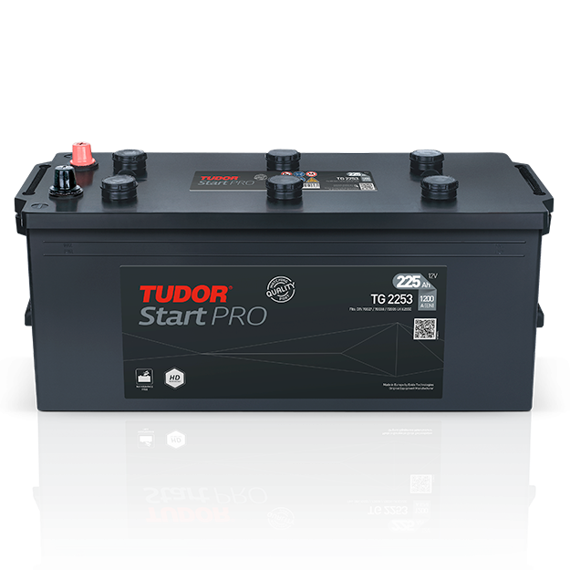
Tudor StartPRO | Exide

Characteristics of an Ideal Battery | Download Scientific Diagram

Battery with internal resistance

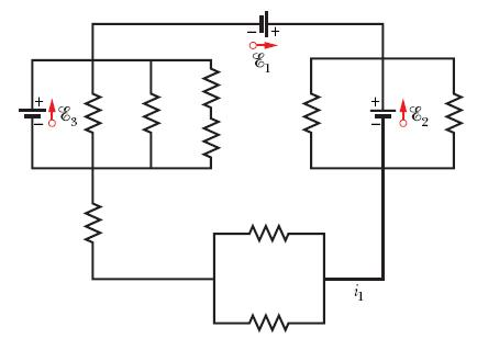
A circuit consisting of three ideal batteries with voltages E1, E2 &, and  E3, and three ideal resistors with resistances R1, R2, and R3, is shown in  the figure. Calculate the current
A circuit consisting of three ideal batteries with voltages E1, E2 &, and E3, and three ideal resistors with resistances R1, R2, and R3, is shown in the figure. Calculate the current

Battery voltage and capacity in non-equilibrium | PVEducation

ipower Ideal Black Coloured Lead Acid Rechargable Battery : Amazon.in:  Electronics
ipower Ideal Black Coloured Lead Acid Rechargable Battery : Amazon.in: Electronics

Solved In the figure the ideal batteries have emfs ε1 = 18.1 | Chegg.com

The ideal battery in Figure a has emf E = 6.0V . Plot 1 in Figure b gives  the electric potential difference V that can appear across resistor 1  versus the current
The ideal battery in Figure a has emf E = 6.0V . Plot 1 in Figure b gives the electric potential difference V that can appear across resistor 1 versus the current

Li-ion, Lead acid, NiMH, redox-flow, etc - Isn't there just one ideal  battery?
Li-ion, Lead acid, NiMH, redox-flow, etc - Isn't there just one ideal battery?

In the figure below, R1 = 100 ohms, R2 = R3 = 50.0 ohms, R4 = 75.0 ohms,  and the ideal battery has an emf E = 6.00 V. What is the current in the  resistor R1? | Homework.Study.com
In the figure below, R1 = 100 ohms, R2 = R3 = 50.0 ohms, R4 = 75.0 ohms, and the ideal battery has an emf E = 6.00 V. What is the current in the resistor R1? | Homework.Study.com

Duracell Automotive - Car batteries

Non Ideal Batteries in Electric Current | Physics Forums

Real vs. Ideal Batteries Capacitance - ppt download

Lithium Ion Polymer Battery Ideal For Feathers - 3.7V 400mAh : ID 3898 :  $6.95 : Adafruit Industries, Unique & fun DIY electronics and kits
Lithium Ion Polymer Battery Ideal For Feathers - 3.7V 400mAh : ID 3898 : $6.95 : Adafruit Industries, Unique & fun DIY electronics and kits
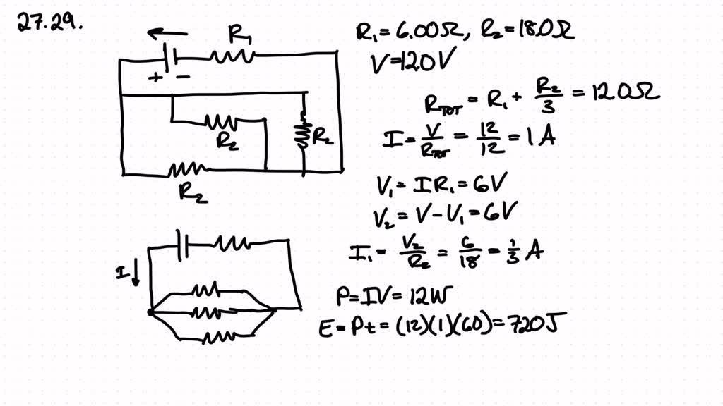
SOLVED:In Fig. 27-40, R1=6.00 ΩR2=18.0 Ω, and the ideal battery has emf  𝒢=12.0 V . What are the (a) size and (b) direction (left or right) of  current i1 ? (c) How
SOLVED:In Fig. 27-40, R1=6.00 ΩR2=18.0 Ω, and the ideal battery has emf 𝒢=12.0 V . What are the (a) size and (b) direction (left or right) of current i1 ? (c) How
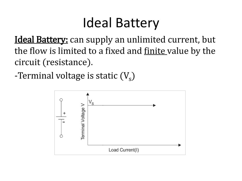
Ideal Battery
Ideal Battery

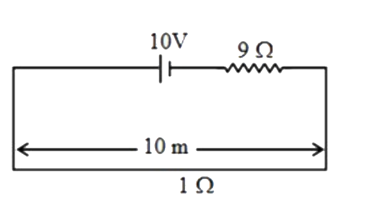
If a ideal battery of e.m.f.10 V is connected with external resistance  9Omega and a wire of length 10 m and resistance 1Omega in series as shown  in potentiometer wire
If a ideal battery of e.m.f.10 V is connected with external resistance 9Omega and a wire of length 10 m and resistance 1Omega in series as shown in potentiometer wire

a) shows the ideal battery model, which consists just of a voltage... |  Download Scientific Diagram
a) shows the ideal battery model, which consists just of a voltage... | Download Scientific Diagram